This is my forum for telling the world
what's
keeping me busy these days.

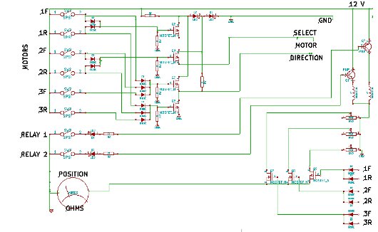
Control schematic
This is the final schematic, for the controller.
Items from the left edge to the middle are in the control box, and
those to the right are in the tuner unit in the other room.The 6
upper-most
switches on the left are used to move the capacitors and the roller
inductor, with position feedback showing on the ohmmeter.The 2 LED's at
the top center are used to set the mid and high voltages, approximately
2 and 4 volts. The resistor below the LED's sets the motor direction
line to mid voltage. The LED's connected to the relay 1 and 2 switches
indicate when the relays are live, and are powered "for free" by base
current from the relay driver transistors.The 3 variable resistors on
the right are each attached to a tuning device, and they are connected
to the ohmmeter through FET's that are switched by the motor logic
signals.The ohmmeter is a DVM that is sold at Harbor Freight
that, a couple times a year, sells for about $2.00 US. A typical panel
meter sells for ten times that. I have 3 more of them just waiting to
go into projects.
| Previous
page |
Next page |
Questions?
Comments? Email me - jim (at) jimdaldry.com