This is my forum for telling the world
what's
keeping me busy these days.

Antenna Tuner Controller
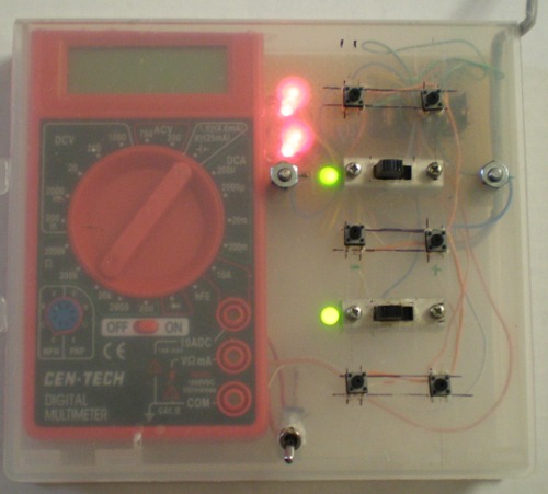
This is the controller. I built it in a box made
for original Nintendo game rentals. The 2 buck meter is proudly
displayed, with its toggle switch for power.I cut one of the battery
leads to add the switch, so I wouldn't have to open the box up every
time I wanted to change the tuner settings. I have to use the battery
since the battery isn't connected to meter ground.
The 2 red LED's are the voltage regulators for the motor control signals. The green LED's are showing that both relays are turned on. The momentary switches are for the 2 capacitors and the roller inductor, increase and decrease in value.While one of the buttons is pressed the ohmmeter indicates the position of the device being adjusted.
Any questions or comments? Want to know why I chose to use the circuits and parts I did? Email me - jim (at) jimdaldry.com. I'll post interesting comments, rants, "you shoulda done it this way, Idiot" stuff on my forum page. If requested, I might even produce some 1024 X 768 schematics over on the picture pages so they can actually be read.
| Previous
page |
Home |
Questions?
Comments? Email me - jim (at) jimdaldry.com