This is my forum for telling the world
what's
keeping me busy these days.

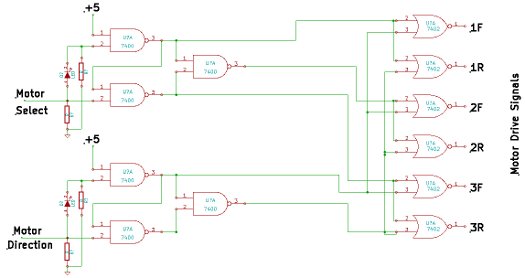
Motor logic schematic
This is the schematic for the motor logic board.
Controlling 3 motors and 2 relays, plus providing for position
feedback, all through an 8 wire cable, required reducing the motor
control signals to 1 wire to select the motor and 1 wire for motor
direction. This requires 3 level logic, low, mid, high. Since TTL chips
call a 1 volt level "high", I was able to separate mid and high by
using an LED. On the input lines, the lower gates see a high if the
input line is from 1 volt to 5 volts. The upper gate, since its input
is through an LED, needs over 3 volts for high. The lower gate output
goes low with an input of between 1 and 3 volts. At 3 volts, the upper
gate output goes low, causing the lower gate output to go high. When
the input wire is below 1 volt both left gate outputs are high, so the
output of the gate to the right is low. So for 3 levels on an input
wire there are 3 separate low outputs. On the right side of the
schematic a low on a select gate and a low on a direction gate are
combined to make a high on a motor drive wire. Since there is no mid
signal decoded in the motor direction cluster, as long as the direction
wire is at mid the motors are off.
| Previous
page |
Next page |
Questions?
Comments? Email me - jim (at) jimdaldry.com