This is my forum for telling the world
what's
keeping me busy these days.

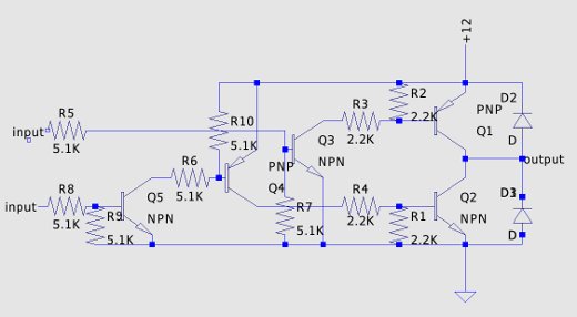
Motor drive schematic
This is the schematic for one half of a motor
drive. The motor is connected between the outputs of 2 of these
circuits, and the inputs are cross-connected. When the input to R5 has
more than about 1 and a half volts applied to it Q1 is driven into
saturation and the output connection is raised to within a couple
tenths of a volt of the supply voltage. If R8 is driven, Q2 is
saturated and the output is within .2 volts of ground. Diodes D2 and D3
catch any reactive "kicks" from the motors. By using a grounded emitter
output amplifier, I was able to get 11.6 volts across the motor with a
12 volt supply. If I had wired it as an emitter follower, the output
would be about 10 volts. The inputs are easily driven by standard logic
IC's.
The NPN transistors are 2N3904's, and the PNP's are 2N3906's. The diodes are 1N4002's. The transistors are prime parts from Dan's Small Parts. The resistors and diodes are from "grab bag" packages from the same source.
The NPN transistors are 2N3904's, and the PNP's are 2N3906's. The diodes are 1N4002's. The transistors are prime parts from Dan's Small Parts. The resistors and diodes are from "grab bag" packages from the same source.
| Previous
page |
Next page |
Questions?
Comments? Email me - jim (at) jimdaldry.com