This is my forum for telling the world
what's
keeping me busy these days.

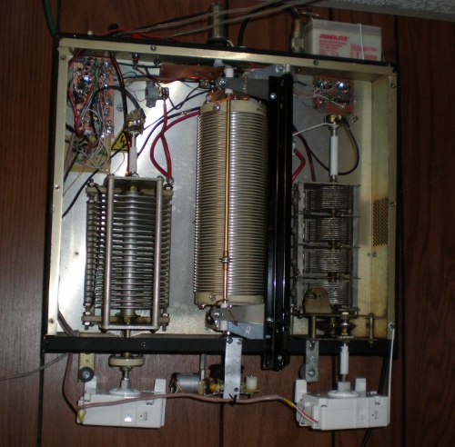
This is the antenna tuner mounted on the wall in the utility room.
The
4 gangs of capacitor C2 are connected in parallel, making it a moderate
voltage 2000 pf variable. The tuner is an L network, with C2 switched
in and out with a relay. Since C2 is only used when the impedance is
low, its voltage rating isn't a problem.
Position feedback for each of the active devices is provided by potentiometers. There is a common 5 k ohm volume control attached to the rear of each of the capacitors, and barely visible at the top center is a 10 turn 1 k ohm pot connected to the roller inductor through an 8 to 1 gear train. I tried to set up feedback for the inductor using a 64 to 1 gear train and optical couplers, but due to gear lash it was impossible to synchronize the bit flip at 32 turns with the flip on the least significant bit. Maybe I'll do it sometime with a couple 4 bit up - down counters, but for now the pot and gears works. When any of the motors is powered the corresponding pot is connected to the indicator line through an enhancement mode FET.
Position feedback for each of the active devices is provided by potentiometers. There is a common 5 k ohm volume control attached to the rear of each of the capacitors, and barely visible at the top center is a 10 turn 1 k ohm pot connected to the roller inductor through an 8 to 1 gear train. I tried to set up feedback for the inductor using a 64 to 1 gear train and optical couplers, but due to gear lash it was impossible to synchronize the bit flip at 32 turns with the flip on the least significant bit. Maybe I'll do it sometime with a couple 4 bit up - down counters, but for now the pot and gears works. When any of the motors is powered the corresponding pot is connected to the indicator line through an enhancement mode FET.
| Previous
page |
Next page |
Questions?
Comments? Email me - jim (at) jimdaldry.com